CYPECAD MEP is a program for the design of the envelope, distribution and services of the building using an integrated 3D model with the various elements of the building. The English version of CYPECAD MEP designs air conditioning installations and carries out dynamic fire simulations in buildings.
CYPECAD MEP is a program for the design of the envelope, distribution and services of the building using an integrated 3D model with the various elements of the building. The English version of CYPECAD MEP designs air conditioning installations and carries out dynamic fire simulations in buildings.
CYPECAD MEP contemplates the following types of buildings: Household (detached, terraced, multi-family) Commercial, Administrative, Residential, Car park, Public attendance, Teaching, Hospital and Industrial.
CYPECAD MEP can be located in the Building services group of the CYPE main program menu. Including
Cooling and heating thermal loads
HVAC systems: hydronic (fan coils and AHUs), direct expansion (splits, VRF) and air (rooftop)
Heating systems with radiators and electric emitters Boilers
Analysis and design of pipes and ducts
Radiant and cooling floor
Geothermal energy harvesting systems
All the building services in a single file
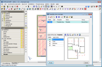
All the installations or checks contemplated by CYPECAD MEP can be introduced in a single file. The program contains several tabs at the bottom part of the screen where the specific data for each installation is introduced.
The floors and construction elements that are defined are common to all the installations and can be introduced in any of the tabs of CYPECAD MEP. This way they are available for each installation without the need of having to define them several times. Floors can be copied or grouped, which saves a lot of time when there are floors which are the same or similar to one another.
Import of IFC files generated by CAD/BIM programs
CYPECAD MEP can import files with IFC format which have been generated by CAD/BIM programs such as Allplan™, Archicad™ and Revit™ Architecture, thanks to the Import of CAD/BIM model module.
This possibility allows CYPECAD MEP to access programs with BIM (Building Information Modelling) technology and therefore, automatically incorporate the construction elements making up the building.
The exact composition of the façades and partitions (conductivity properties of each layer, position of the vapour barrier, thermal bridges, etc.) is not usually specified during the design process of the building. CYPECAD MEP incorporates an IFC format model import assistant, which allows users to automatically assign the properties of the façades, internal partitions, floor slabs, roofs, windows, etc. This way, users of the CAD/BIM program are not obliged to provide a detailed description of each element and so an effective separation between the design and technical specification is obtained for the phases of each component. Additionally, the materials are easily selected in CYPECAD MEP.
Export to IFC format
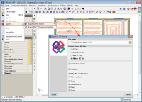
CYPECAD MEP allow for the introduced construction elements and designed building services to be exported to an IFC (Industry Foundation Classes) format file. This way, the information that has been introduced and generated in CYPECAD MEP can be read in CAD/BIM programs such as Allplan™, Archicad™, Revit™ Architecture, etc.
The option to Export in IFC format (File > Export) has been implemented in all the modules of CYPECAD MEP. This option opens a dialogue box where user can choose which elements are to be exported:
Construction elements
Installation
Only Air conditioning
All the installations
Only the indicated installation elements:
Groups
Linear elements
Pipes
Ducts
When exporting, users can also choose the type of IFC file (IFC 2×3, Archicad IFC 2×3, Revit IFC 2×3 or Allplan IFC 2×3) and the directory where it will be saved.
Users are not required to have the CAD/BIM model import module in their user license for CYPECAD MEP to export the job in IFC format.
Manual data entry
If users choose not import the construction elements using an IFC file which has been generated by a CAD/BIM program, these can be defined manually, with or without the help of drawing files with DXF, DWG, JPEG, JPG, BMP, WMF, EMF or PCX format.
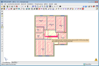
CYPECAD MEP uses a floor-by floor data entry method for which users define:
The building elevation configuration (number of floor groups and their heights)
The construction elements of the building (walls, partitions, floor slabs, openings…)
The distribution of the installation on plan and distribution of the elements it is composed of.
The installation can connect different floors. Elevation changes can also be defined within them.
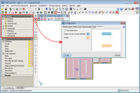
All of CYPECAD MEP’s modules contain an assistant to guide users in introducing the general data of the project.
Users can use a DXF or DWG template (with object snap options) to help users to introduce the construction elements and distribution of the installation. Drawing files: JPEG, JPG, BMP, WMF, EMF and PCX can also be imported and used as templates to introduce the geometry on plan of the installation, although due to the format of the files, objects snaps are not available. Nonetheless, this option can be useful when great precision is not required and drawings on paper are available, which can be scanned to easily obtain drawing files with these formats.
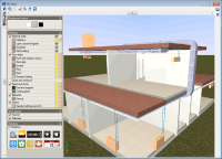
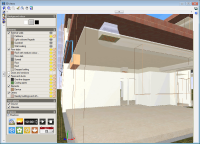
This working methodology, which is common to all the modules of CYPECAD MEP, allows users to edit the plans of the installation directly and, at the same time, manage the geometry in a completely integrated manner, allowing for 3D views to be generated of the complete installation.
Construction element introduction
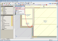
Users can introduce construction elements in CYPECAD MEP by layers or elements.
Network introduction
All the installation and construction elements on plan or selected elements can be moved, duplicated, rotated or create symmetrical reflections.
A range of tools are available to aid in and provide a precise introduction of the geometry of all the installations (force cursor, object references, tracking, coordinate confirmation…).
A section can be dropped to the bottom part of the screen providing instructions on the use of the menu options to help users.
Elevation DXF
Riser pipes can be situated on an elevation DXF to obtain the corresponding elevation drawing.
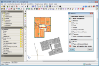
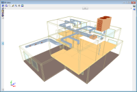
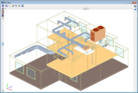
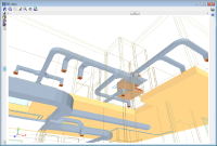
3D views
The complete network (all floors) can be seen in a 3D view.
The 3D views can be visualised in conical or isometric perspective.
Users can move freely within the structure when viewed in conical perspective. Any 3D view can be made transparent or opaque allowing hidden elements to be seen easily.
Elements within the 3D views can be displayed with textures resembling the real colour of their materials. Users can choose whether or not the 3D view is to display the materials.
Analysis
The program will check the network with the indicated data and will design it, if required. After the analysis, the results which have been obtained can be checked. If any problems have been encountered in the design, the program generates a warning message for those cases in which incidents have been found but does not invalidate the design of the installation, and error messages for those in which the problem causes an incorrect design of the installation.
For a quicker design, when a job includes several installations, the program can carry out an automatic analysis for all of them. This way, if one piece of data is modified, and affects several installations (location, construction element, etc.), all the analyses are carried out without the need of having to initiate the analysis of the installation at its corresponding tab or wait for one to finish before manually initiating the next. The option Analysis of all the installations carries out the process for all the installations of the job. When this analysis has finished, a dialogue box appears indicating:
The installations that have been analysed correctly
The installations which have not been analysed because no elements have been introduced
The installations which contain an error which does not allow the analysis to continue.
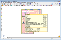
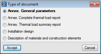
Results, reports and drawings
CYPECAD MEP displays the analysis results and check in an interactive manner using on-screen texts.
It also provides reports, which, after a preliminary view can be printed directly or exported as a text file (TXT), HTML, PDF, RTF or DOCX.
Drawings of the introduced installation can also be obtained for each floor (even superimposed on the template that was used), as well as 3D views, symbol and abbreviation tables, elevation views, etc.
The drawings can then be printed directly (printer or plotter) or exported in DXF or DWG format.
We use cookies on our website to give you the most relevant experience by remembering your preferences and repeat visits. By clicking “Accept All”, you consent to the use of ALL the cookies. However, you may visit "Cookie Settings" to provide a controlled consent.
This website uses cookies to improve your experience while you navigate through the website. Out of these, the cookies that are categorized as necessary are stored on your browser as they are essential for the working of basic functionalities of the website. We also use third-party cookies that help us analyze and understand how you use this website. These cookies will be stored in your browser only with your consent. You also have the option to opt-out of these cookies. But opting out of some of these cookies may affect your browsing experience.
Necessary cookies are absolutely essential for the website to function properly. These cookies ensure basic functionalities and security features of the website, anonymously.
Cookie
Duration
Description
cookielawinfo-checkbox-analytics
11 months
This cookie is set by GDPR Cookie Consent plugin. The cookie is used to store the user consent for the cookies in the category "Analytics".
cookielawinfo-checkbox-functional
11 months
The cookie is set by GDPR cookie consent to record the user consent for the cookies in the category "Functional".
cookielawinfo-checkbox-functional
11 months
The cookie is set by GDPR cookie consent to record the user consent for the cookies in the category "Functional".
cookielawinfo-checkbox-necessary
11 months
This cookie is set by GDPR Cookie Consent plugin. The cookies is used to store the user consent for the cookies in the category "Necessary".
cookielawinfo-checkbox-others
11 months
This cookie is set by GDPR Cookie Consent plugin. The cookie is used to store the user consent for the cookies in the category "Other.
cookielawinfo-checkbox-performance
11 months
This cookie is set by GDPR Cookie Consent plugin. The cookie is used to store the user consent for the cookies in the category "Performance".
viewed_cookie_policy
11 months
The cookie is set by the GDPR Cookie Consent plugin and is used to store whether or not user has consented to the use of cookies. It does not store any personal data.
Functional cookies help to perform certain functionalities like sharing the content of the website on social media platforms, collect feedbacks, and other third-party features.
Performance cookies are used to understand and analyze the key performance indexes of the website which helps in delivering a better user experience for the visitors.
Analytical cookies are used to understand how visitors interact with the website. These cookies help provide information on metrics the number of visitors, bounce rate, traffic source, etc.
Advertisement cookies are used to provide visitors with relevant ads and marketing campaigns. These cookies track visitors across websites and collect information to provide customized ads.